Ball valves KM are characterized by robust design designed with respect to as longest as possible lifetime and durability. Rolled or forged steel is used for production of pressure-retaining components. The main parts are body, body cover with ends for connection of the ball valve to the piping, ball, seats and stem.
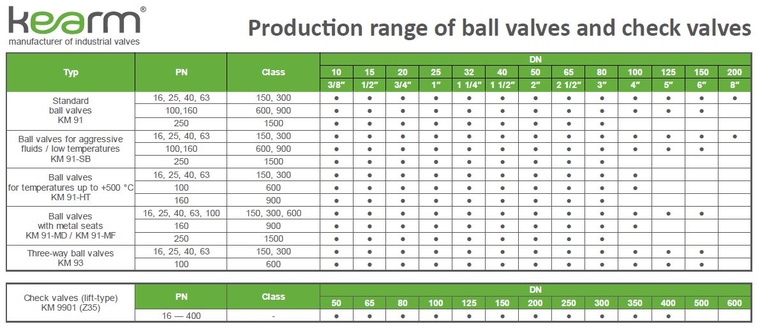
The ball valves are supplied in two series as a standard:
The valve bore in open position conforms to EN 1983 or API 608 (for valves according to American standards). The ball valves are supplied with full bore as a standard feature or with reduced bore upon request. The stem design ensures that the stem can not be ejected from the valve body by pressure of the fluid (anti-blow-out stem), internal components are connected to provide conductivity and resistance to formation of electrostatic discharges (anti-static design).
The ball valves can be equipped with the following ends for connection to the piping:
The standard design of the closure system is a floating ball supported by two seats which provides for tightness in the downstream seat. The ball valve can be supplied with doubled sealing effect as well, i.e. with simultaneous seal against pressure in both seats (so-called double-block-and-bleed (DBB) and double-piston (DP) effect).
The stems of ball valves for normal temperatures are sealed with a combination of O-rings and PTFE rings as a standard feature, for high temperatures a graphite packing is used, for very low temperatures a PTFE packing is used.
The ball valves are operated manually as a standard, by turning the lever through an angle of 90°. The end positions are limited by stops. Ball valves of bigger sizes and for higher pressures are operated by a gearbox with a handwheel. If required by the customer, ball valves can be equipped with electric or pneumatic actuators. The actuator size depends on the maximum pressure drop through the ball. Dimensions of flanges for actuator installation are in accordance with ISO 5211.
Ball valves are manufactured with the following standard materials of the body:
1.4541 as a standard, equivalent of ČSN 17 246, ASTM A182 F321, A182 F304 steels
(for temperatures from −200 °C to +500 °C), 1.4571 as a standard, equivalent of ČSN 17 346, ČSN 17 348, ASTM A182 F316Ti steels
By mutual agreement and based on service conditions, also other body materials may be used (e.g., austenitic stainless steels with low carbon content, duplex stainless steels, Super Duplex, Hastelloy® C-276, Monel, 1.4306, 1.4539, 1.4410, 16Mo3 etc.).
Materials for all pressure-retaining components are purchased with
3.1 certificate according to EN 10 204.
Ball valves described in this catalogue are isolating valves designed to be used to open or close the service fluid flow in the piping fully. The scope of application of the ball valves depends directly on their materials and type.
The ball valves are intended to be used with a wide range of fluids, especially heating gases (natural gas, lighting gas, propane-butane mixture, biogas, coke-oven gas), water, steam, oxygen, and both corrosive and non-corrosive liquids and gases in general.
The ball valves are approved in accordance with the Decree of the Government No. 219/2016 Coll., and in accordance with the Directive 2014/68/EU of the European Parliament and of the Council, as pressure equipment within the meaning of piping and pressure equipment for the use of fluids in group 1 (hazardous fluids under a special legal regulation – Regulation of the European Parliament and of the Council No 1272/2008) and in group 2 (other fluids not listed in group 1).
The following has to be investigated to determine the suitability of application of a specific ball valve type for specific parameters of the fluid:
on components being in contact with the fluid. These are:
In order to assess the corrosive effects of the fluid properly, the chemical composition of the fluid (including concentrations of individual constituents) and the range of service temperatures have to be known. The company KE-ARM is in possession of an extensive database of information about corrosive effects of fluids on different materials and is able to suggest such a ball valve type to the customer which meets all specified parameters at the most favourable price.
The body, the seat and the elastomer seals used in the ball valve shall simultaneously withstand the required service pressure at the service temperature
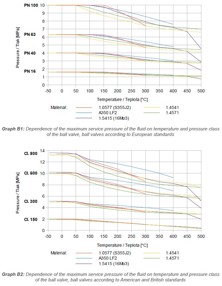
The maximum allowable service pressure of the fluid in the ball valve is shown for specific materials, temperatures and pressure classes PN or Class in the graphs below.
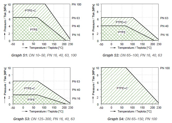
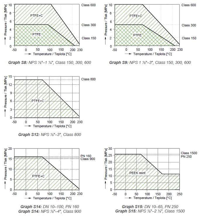
The maximum allowable pressure of the fluid on the ball in ‚closed‘ position is shown for specific seat materials, temperatures, pressure classes PN or Class, and nominal sizes DN in the graphs below. The graphs apply to ball valves with seats made of PTFE, PTFE+C (RPTFE) and PEEK. Ball valves with carbon seats (series “HT”, formerly “03.1”) and metallic seats (series “MDX” and “MFX”) require no assessment of effects of pressure on the seats. Graph for PTFE+C applies to ball valves with metallic seats (series “MX”) as well. In case of ball valves with reduced bore, the DN values in the graphs apply to the ball. Depending on the type of valve, the values in the tables may vary slightly, therefore the required maximum working pressure of the seat at the maximum operating temperature of the valve should be given in the purchase order. This value will then be listed in the test report of the valve.
In case of application of elastomer sealing rings we supply these materials:
In case of large orders, also special materials can be supplied, e.g. HNBR,
EPDM, FPM, FFKM for different limit temperatures (e.g. −50 °C, +
280 °C).
KM 9ABC.D-EF…, where:
A – character of flow profile
1 – straight pattern ball valve
3 – three-way ball valve
4 – four-way ball valve
B – character of operation
0 – operation by lever
3 – operation by gearbox or actuator (or only ready for installation of
gearbox or actuator)
C – character of connection to the piping
1 – internal thread
2 – external thread
3 – weld end
7 – wafer type
8 – flanges
D – character of material variant
1 – carbon steel for normal temperatures
3 – corrosion-resisting austenitic chrome-nickel stainless steel
4 – corrosion-resisting austenitic chrome-nickel-molybdenum stainless
steel
5 – carbon steel for low temperatures
8 – alloyed steel for high temperatures
9 – steels or alloys with specific properties
EF… – additional characters for more detailed specification of the type
All ball valves are subject to the following tests as a standard:
If required by the customer, additional tests may be performed as well.
The following documentation is delivered together with the ball valve as a standard:
Additional documents as required by the customer (i.e. certificate according
to EN 10 204 3.2).
Spare parts can be supplied according to an agreement with the customer (i.e.
sealing material).
Standard guarantee period is 24 months from receipt of goods.
The ball valves may be installed into the piping in any arbitrary position. They require no special adjustments or maintenance. They are operable at the full pressure drop which equals to PN (or the corresponding pressure Class). The operability depends essentially on the service life of the ball sealing system and the stem sealing system, it means that of the seats and the rubber O-rings (if used). The service life of metal parts of the body, the ball and the stem is at least 20 years. The service life (functional ability) of PTFE seats and rubber O-rings is at least 5000 cycles of ‚open-close‘; if the ball is operated infrequently, their service life (to the first leakage) is given by the service life of the rubber, i.e. at least 3 years. However, the parameters of the fluid as confirmed in the purchase contract (temperature, pressure, chemical composition, concentration, purity) have to be maintained.
When welding the ball valves type KM 9103.X-01 into the pipeline, the following procedure must be followed:
The following information shall be supplied in the purchase order: